Different Types of Solder Paste: IPC Grades, Alloys, and Selection Guide
-
2026-07-22 Industry News






Learn different types of solder paste including IPC classifications and alloy options, and how to select the right paste for SMT manufacturing and assembly performance.
Introduction
Solder paste is a critical material in the SMT reflow soldering process. Its performance not only affects the quality of solder joints but is also closely related to production efficiency, process stability, and product reliability. When faced with different electronic products, packaging formats, and manufacturing requirements, selecting the appropriate solder paste often requires a comprehensive consideration of multiple factors, including alloy systems, process conditions, and end applications.
Currently, solder pastes commonly used in the industry can be classified based on multiple dimensions, including alloy systems, flux types, and powder particle size. Additionally, with the development of power semiconductors and advanced packaging technologies, sintered interconnect materials have gradually become an important choice for certain applications. Therefore, establishing a clear classification framework helps to more accurately understand the characteristics and suitable applications of different materials.
This article will cover the composition of solder paste, mainstream tin-based solder paste systems, sintered interconnect materials, IPC particle size grades, and selection methods. By referencing relevant industry standards, it aims to help readers gain a more systematic understanding of the differences between various solder pastes and provide guidance for material selection in electronics manufacturing.
Basic Composition and Classification Dimensions of Solder Paste
1. Components of Solder Paste
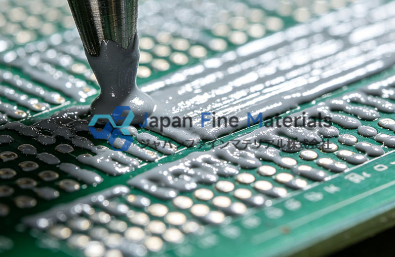
Solder paste used in SMT reflow soldering typically consists of solder powder and a flux system, along with solvents, resins, and small amounts of functional additives. These components collectively determine the solder paste’s printing performance, reflow characteristics, and joint quality.
|
Components |
Primary Function |
|
Solder Powder |
Melts to form solder joints, providing mechanical and electrical connections |
|
Flux |
Removes oxidation layers from the surfaces of pads and components, improving wettability |
|
Solvents and Carriers |
Adjust the viscosity of the solder paste to ensure optimal stencil printing performance |
|
Functional Additives |
Improve sag resistance, printing stability, storage performance, and reflow performance |
During the SMT production process, solder paste is first printed onto the PCB pads through a stencil, followed by component placement, and then heated in a reflow oven to melt the solder and form solder joints.
Throughout this process, solder paste not only affects the appearance of the solder joints but also directly influences soldering defects such as bridging, voids, tombstoning, and insufficient wetting; therefore, its performance must be compatible with the PCB design, component packaging, and reflow process.
2. Classification Criteria for Solder Paste
Classification by Alloy System
This is a common classification method in electronics manufacturing and will be the focus of the remainder of this article. Common alloy systems include:
• Tin-Silver-Copper (SAC)
• Tin-Copper (Sn-Cu)
• Tin-Bismuth (Sn-Bi, Sn-Bi-Ag)
• Tin-lead (Sn-Pb)
Different alloy systems have varying melting points, wetting properties, mechanical strength, and thermal cycling performance, making them suitable for different products and process requirements.
Classification by Process Temperature
Solder paste can also be classified based on reflow temperature, for example:
|
Classification |
Typical Characteristics |
Common Alloys |
|
Standard Reflow Solder Paste |
Suitable for standard SMT reflow processes |
SAC305, Sn0.7Cu |
|
Low-Temperature Solder Paste |
Reduces peak reflow temperature and minimizes thermal stress |
Sn42Bi58, SnBiAg |
It should be noted that low-temperature solder paste is not a standalone material system, but rather a specific application category within tin-based solder pastes. For example, the Sn-Bi series essentially remains a tin-based alloy, albeit with a lower melting temperature, and is therefore typically used exclusively in low-temperature reflow processes.
Classification by Flux System
The flux system primarily affects the residue left by the solder paste after reflow and the subsequent cleaning requirements. Common types include:
• No-Clean Solder Paste
• Water-soluble solder paste
• Rosin-based solder paste
For example, no-clean solder paste is commonly used in consumer electronics to reduce the need for cleaning; however, for certain high-reliability electronic products, a post-reflow cleaning solution may be selected based on process requirements.
Therefore, “no-clean” refers to a classification within the flux system rather than an alloy classification.
Classification by Solder Powder Particle Size
As electronic products continue to evolve toward higher density and smaller sizes, solder powder particle size has also become an important factor affecting printing quality.
IPC standards classify solder paste into different grades—such as Type 3, Type 4, Type 5, and Type 6—based on solder powder particle size, with different particle sizes suitable for different stencil aperture sizes and component packages.
This article will provide a detailed introduction to particle size grades and their application differences in subsequent sections.
3. Logic Behind Solder Paste Classification
Since solder paste can be classified along multiple dimensions, mixing different standards can easily lead to conceptual overlap. For example, comparing “tin-based solder paste,” “low-temperature solder paste,” and “no-clean solder paste” at the same level corresponds to three distinct dimensions—alloy composition, process temperature, and flux system—which hinders the development of a comprehensive technical understanding.
Therefore, this article will follow the logic outlined below:
• Using alloy systems as the main thread, this paper introduces common tin-based solder pastes used in SMT reflow soldering;
• Provide a separate discussion of sintered interconnect materials, highlighting their process differences from traditional reflow solder pastes;
• Analyze the relationship between different particle size grades and the printing process in conjunction with IPC standards;
The Mainstream in SMT Reflow Soldering: Tin-Based Solder Paste Systems
In modern electronic assembly, the vast majority of SMT reflow soldering processes use tin-based solder paste. The term “tin-based” refers to tin (Sn) as the primary component of the alloy, with elements such as silver (Ag), copper (Cu), bismuth (Bi), or lead (Pb) added according to specific application requirements to achieve different melting points, wetting properties, and reliability performance.
Currently, the most common tin-based solder pastes in the industry fall into four major categories: tin-silver-copper (SAC), tin-copper (Sn-Cu), tin-bismuth (Sn-Bi), and tin-lead (Sn-Pb).
1. Tin-Silver-Copper (SAC) — The Mainstream Solution for Lead-Free SMT
Tin-silver-copper solder paste (Sn-Ag-Cu), commonly abbreviated as SAC solder paste, is one of the most widely used alloy systems in lead-free SMT reflow soldering today. With the global implementation of RoHS regulations across the electronics manufacturing industry, the SAC series has gradually become the mainstream choice in consumer electronics, industrial electronics, and automotive electronics.
Common grades include:
• SAC305 (Sn 96.5/Ag 3.0/Cu 0.5)
• SAC0307 (Sn 99.0/Ag 0.3/Cu 0.7)
• SAC405 (Sn 95.5/Ag 4.0/Cu 0.5)
Different formulations vary in terms of silver content, cost, and soldering performance; companies typically select the appropriate grade based on product positioning and process requirements.
Key Features of the SAC Series
• Good wetting properties, which facilitate the formation of uniform solder joints
• Good mechanical strength and thermal fatigue resistance
• Compatible with mainstream lead-free reflow soldering processes
• A well-established supply chain and extensive application experience
|
Alloy Grade |
Typical Melting Point |
Key Features |
Common Applications |
|
SAC305 |
217–220°C |
Well-balanced overall performance |
Consumer electronics, industrial electronics |
|
SAC0307 |
Approx. 227°C |
Low silver content, cost-effective |
High-volume electronics manufacturing |
|
SAC405 |
Approx. 217°C |
Higher silver content, better thermal fatigue performance |
Electronic products with high reliability requirements |
2. Tin-Copper (Sn-Cu) Series — A Low-Cost Solution
Tin-copper (Sn-Cu) solder paste is another common type of lead-free tin-based solder paste, with tin (Sn) and copper (Cu) as its primary alloying elements. Compared to the SAC series, the Sn-Cu system does not contain silver, resulting in relatively lower material costs. It has found some application in certain cost-sensitive or process-mature electronic manufacturing scenarios.
Common grades in the industry include Sn99.3Cu0.7 (Sn0.7Cu) and others, with a liquidus temperature of approximately 227°C, making them suitable for standard lead-free SMT reflow soldering processes.
It should be noted that Sn-Cu belongs to the tin-based solder paste category and is not a “copper solder paste.” Although copper is added to the alloy, tin remains the primary component; therefore, it should be classified as a tin-based alloy.
Characteristics of Sn-Cu Solder Paste
• Relatively simple alloy composition and lower material costs
• Meets the requirements of most standard SMT reflow soldering processes
• Electrical conductivity and soldering performance meet the requirements for general electronic product applications
• Suitable for established lead-free production processes
Compared to the SAC series, Sn-Cu solder paste may exhibit certain differences in thermal fatigue performance and wetting behavior; therefore, for applications involving long-term thermal cycling or high reliability requirements, a comprehensive evaluation based on the product’s operating environment is typically necessary.
3. Tin-Bismuth (Sn-Bi / Sn-Bi-Ag) — The Low-Temperature Branch of Tin-Based Solder Pastes
With the continuous development of flexible electronics, miniaturized components, and heat-sensitive elements, an increasing number of products aim to lower reflow temperatures to reduce thermal stress on PCBs and components. Against this backdrop, tin-bismuth (Sn-Bi) solder paste has gradually become an important material for low-temperature SMT reflow soldering.
It is important to emphasize that low-temperature solder paste is not a separate material category, but rather an application branch within tin-based solder pastes. Currently, low-temperature solder pastes commonly used in the industry primarily employ tin-based alloy systems such as Sn-Bi or Sn-Bi-Ag.
Among these, Sn42Bi58 is a widely used low-temperature eutectic alloy with a melting point of approximately 138°C, which is significantly lower than that of the SAC series, enabling soldering to be completed at lower peak reflow temperatures.
Key Features of the Sn-Bi Series
• Lower reflow temperature, which reduces thermal shock
• Helps reduce PCB warpage and thermal effects on certain heat-sensitive components
• Suitable for temperature-sensitive electronic products
• Can be used in conjunction with certain low-temperature manufacturing processes
|
Alloy System |
Melting Point |
Application Features |
|
Sn42Bi58 |
Approx. 138°C |
Common Low-Temperature Reflow Schemes |
|
Sn-Bi-Ag |
Slightly higher than Sn-Bi |
Improves certain mechanical properties compared to the low-temperature formulation |
4. Tin-Lead (Sn-Pb) — Still Used in RoHS-Exempt Applications
Prior to the implementation of RoHS regulations, tin-lead (Sn-Pb) solder paste had long served as the mainstream soldering material in the electronics manufacturing industry. Among these, the Sn63Pb37 eutectic alloy was widely used in the manufacture of various electronic products due to its stable melting point, good wetting properties, and wide process window.
With the development of lead-free processes, most consumer electronics products have now gradually adopted lead-free solder paste. However, in certain RoHS-exempt application areas, tin-lead solder paste still has specific use cases.
Characteristics of Sn-Pb Solder Paste
• Low melting point and mature reflow process
• Good wetting properties and stable solder joint formation
• Relatively wide process window, suitable for established production lines
• Still used in certain specialized industries
|
Alloy |
Melting Point |
Application Notes |
|
Sn63Pb37 |
183°C |
Eutectic alloy, traditional SMT process |
|
Sn60Pb40 |
183–190°C |
Certain traditional electronic products |
Currently, tin-lead solder paste is primarily used in certain RoHS-exempt products, repair and rework processes, or specific industrial applications. When selecting such materials, companies should evaluate them in light of target market regulatory requirements and product compliance standards.
Advanced Packaging for Power Semiconductors: Sintered Interconnect Materials
With the development of new energy vehicles, photovoltaic inverters, energy storage equipment, and industrial power supplies, the application of wide-bandgap semiconductor devices such as SiC (silicon carbide) and GaN (gallium nitride) continues to grow, placing higher demands on the high-temperature resistance, thermal conductivity, and long-term reliability of interconnect materials.
In these advanced packaging applications, an increasing number of companies are adopting sintered interconnect materials. Although these materials are sometimes supplied in paste form, their process mechanisms differ significantly from those of traditional SMT reflow solder paste.
Traditional SMT solder paste relies on the melting of solder to form solder joints, whereas sintered materials cause metal particles to gradually diffuse and form a dense interconnect layer under conditions such as temperature, pressure, and a specific atmosphere.
Although both fall under electronic interconnection technologies, the methods by which they form connections differ.
Therefore, when selecting materials, it is important to first recognize that the two belong to different technological approaches.
1. Silver Sintering Paste
Silver sintered paste is a type of sintered interconnection material widely used in the packaging of advanced power devices.
It typically consists of nanoscale or micrometer-scale silver particles that form a highly dense silver interconnection layer under appropriate temperature and pressure conditions, thereby achieving good thermal conductivity and long-term reliability.
Compared to traditional solder joints, the sintered silver layer has lower interfacial thermal resistance, offering certain advantages in high-power-density devices.
Common Applications
• SiC Power Modules
• IGBT modules
• Power controllers
• Electric drive systems for new energy vehicles
• High-Power Power Modules
Key Features
• Good thermal conductivity
• Suitable for applications with higher junction temperatures
• Helps improve thermal cycling reliability
• Meets certain high-power packaging requirements
It should be noted that silver sintered paste is a sintered interconnect material, not traditional SMT solder paste; the two should not be confused as belonging to the same material category.
2. Copper Sintering Paste
In addition to silver sintering paste, copper sintering paste has also gradually gained attention in the power semiconductor packaging field in recent years.
Copper offers excellent electrical and thermal conductivity, while the cost of raw materials is relatively low, giving it significant application potential in certain high-power device interconnection solutions. However, compared to silver, copper is more prone to oxidation in high-temperature environments, so its sintering process typically requires stricter process control.
Currently, copper sintering pastes generally require a protective atmosphere such as nitrogen or formic acid; some processes also require the application of pressure to promote the formation of a stable metallic bond layer between particles.
Characteristics of Copper Sintering Pastes
• Good thermal and electrical conductivity
• Relatively low raw material costs
• High requirements for sintering atmosphere and process control
• Currently used primarily in research and industrial projects involving the packaging of certain advanced power devices
It is important to note that copper sintering paste is not the same as the “copper solder paste” used in traditional SMT reflow soldering. It is a sintering-type interconnect material, and its process mechanism is entirely different from that of tin-based solder paste; therefore, it should not be confused with Sn-Cu tin-based solder paste when selecting materials.
3. Fundamental Differences Between Sintering Pastes and Reflow Solder Pastes
Although both types of materials are supplied in paste form and used for electronic interconnections, there are significant differences in the manufacturing processes and application scenarios they are designed for.
|
Comparison Points |
Tin-Based Solder Paste |
Sintering Paste |
|
Joining Mechanism |
The alloy melts and solidifies to form a solder joint |
Metal particles diffuse to form a sintered layer |
|
Typical Materials |
SAC, Sn-Cu, Sn-Bi, Sn-Pb |
Silver sintering paste, copper sintering paste |
|
Main Process |
SMT reflow soldering |
Sintering |
|
Common Equipment |
SMT assembly line, reflow oven |
Sintering Equipment, Pressure Sintering Equipment |
|
Application Areas |
PCB Electronic Assembly |
Power Semiconductor Packaging, Advanced Packaging |
For most PCB electronics assembly companies, tin-based solder paste remains the standard material used in daily operations. Sintered interconnect materials, on the other hand, are more commonly used in power semiconductors, advanced packaging, and certain high-power electronic systems, with each corresponding to a distinct technological approach.
Powder Particle Size and Printing Process Compatibility
In addition to the alloy composition, the particle size of solder powder is also a key factor affecting SMT printing quality.
With the increasing prevalence of ultra-small components such as 01005 and 008004, as well as fine-pitch and micro-BGA packages, more and more manufacturers are paying attention to the selection of solder paste particle size grades.
Currently, the industry generally adopts standards such as IPC J-STD-005 and IPC J-STD-006 to specify solder paste performance and solder powder requirements. Among these, solder powder particle size is typically classified into grades such as Type 3, Type 4, Type 5, and Type 6.
1. IPC Standards and Solder Paste Particle Size Grades
During the solder paste selection process, designations such as Type 3 and Type 4 are frequently encountered.
It is important to distinguish between two IPC standards:
IPC J-STD-005
primarily addresses the solder paste product itself, specifying performance requirements, test methods, and quality evaluation criteria for solder paste, such as:
• Viscosity
• Sag resistance
• Wetting performance
• Reflow performance
• Storage stability
This standard helps manufacturers evaluate whether solder paste meets production requirements.
IPC J-STD-006
Primarily specifies the classification methods for solder alloys and solder powders, including:
• Alloy grades
• Chemical Composition
• Solder Powder Particle Size Grades (Type)
Therefore, the classifications we commonly refer to—such as Type 3, Type 4, Type 5, and Type 6—are primarily derived from IPC J-STD-006.
2. Type 3–Type 6 Particle Size Grades and Typical Applications
The finer the solder powder, the more suitable it is for small stencil apertures and high-density PCBs; however, this also places higher demands on storage, printing environments, and process control.
|
IPC Particle Size Grades |
Typical Particle Size (approx.) |
Common Applications |
|
Type 3 |
25–45 μm |
Standard SMT assembly |
|
Type 4 |
20–38 μm |
Fine-pitch PCBs, QFN |
|
Type 5 |
15–25 μm |
Micro-BGA, 01005 components |
|
Type 6 |
5–15 μm |
Ultra-High-Density Advanced Packaging |
In recent years, as electronic products have continued to evolve toward higher integration, the proportion of solder paste applications at Type 4 and above has gradually increased.
However, choosing a finer particle size does not necessarily mean better soldering quality. In practical applications, factors such as stencil thickness, PCB design, component size, and the capabilities of the printing equipment must also be taken into comprehensive consideration.
3. What process controls should be considered for fine-particle solder paste?
Compared to Type 3, Type 5 and Type 6 solder pastes are more sensitive to the production environment due to their finer powder particles and larger specific surface area.
It is generally recommended to focus on the following aspects:
Temperature Recovery Management
After solder paste is removed from a refrigerated environment, it should be allowed to return to room temperature in accordance with the product technical specifications to prevent moisture condensation caused by temperature differences, which could adversely affect printing performance.
Ambient Humidity
Excessively high humidity in the production environment may affect the stability of the flux system and increase the risk of solder oxidation; therefore, the workshop environment should be controlled in accordance with process specifications.
Shelf Life After Opening
Once opened, the performance of solder paste will gradually change over time. In actual production, the usage period should be appropriately scheduled in accordance with the supplier’s technical documentation and on-site management guidelines to minimize material waste and process fluctuations.
Printing Parameters
For fine-pitch and micro-BGA products, process optimization typically requires consideration of the following factors:
• Stencil Thickness
• Slot Design
• Squeegee Pressure
• Printing Speed
• Demolding parameters
These parameters collectively affect solder paste transfer efficiency and joint consistency.
4. Common Issues in Fine-Pitch Printing and Optimization Strategies
As component sizes continue to shrink, solder paste printing quality has become one of the key factors affecting SMT yield.
In actual production, the following issues may arise with fine-pitch PCBs:
|
Common Issues |
Possible Causes |
Optimization Approaches to Consider |
|
Bridging |
Excessive solder paste, incompatible stencil design |
Optimize stencil apertures and printing parameters |
|
Insufficient Solder |
Insufficient Transfer Rate |
Adjust stencil thickness and particle size grade |
|
Sagging |
Insufficient solder paste stability |
Evaluate solder paste performance and environmental conditions |
|
Voids |
Reflow profile or material compatibility issues |
Optimizing the Reflow Process and Material Combinations |
It should be noted that these issues are typically influenced by a combination of factors, including PCB design, component packaging, solder paste performance, and equipment parameters. Therefore, in actual production, validation often requires the use of DOE (Design of Experiments) rather than relying solely on adjustments to a single material.